🛠️ 0 ~ 10 까지 더하는 system 설계하기
어제의 counter를 응용시켜 0부터 10까지의 수를 차례대로 더하는 시스템을 설계해보자.
fnd에 결과로 55가 출력되어야 한다.
1. c언어
adder system을 c언어로 간략하게 동작부분만 나타낼 때 아래와 같이 나타낼 수 있다.
i = 0;
sum = 0;
while (i <= 10){
	sum = sum + i;
	i++;
	out = sum;
}
// out = sum;
halt;
2. datapath diagram
adder와 register의 경우 tr이 많이 필요하므로 가격 절감을 위해 adder를 한개만 사용해 설계하고 싶다.

adder를 하나만 사용하는데, 이때 i = i + 1 과 sum = sum + i를 수행하는 두가지 경우 모두를 위해 mux가 하나 더 사용된다.
3. control unit - asm chart
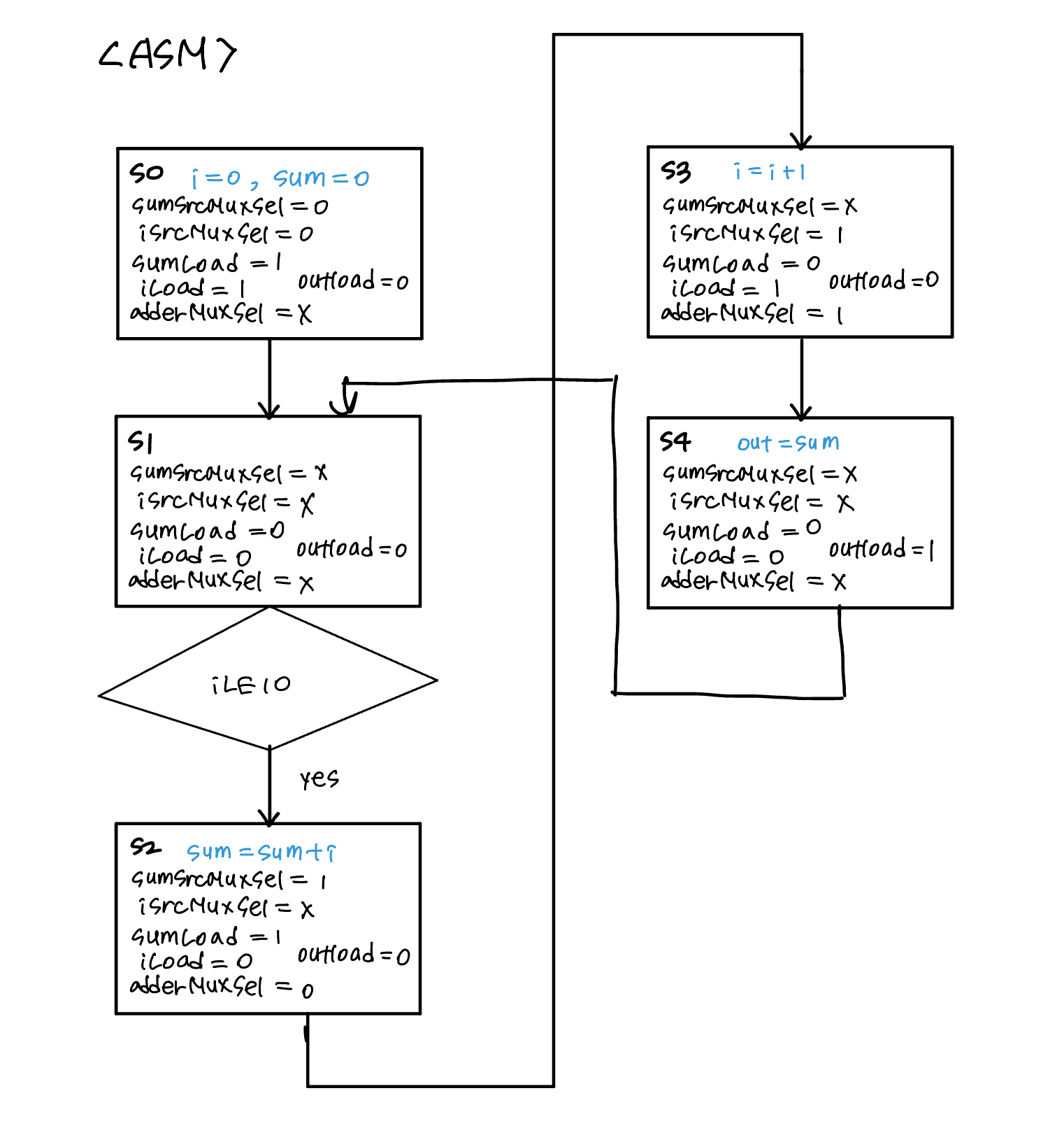
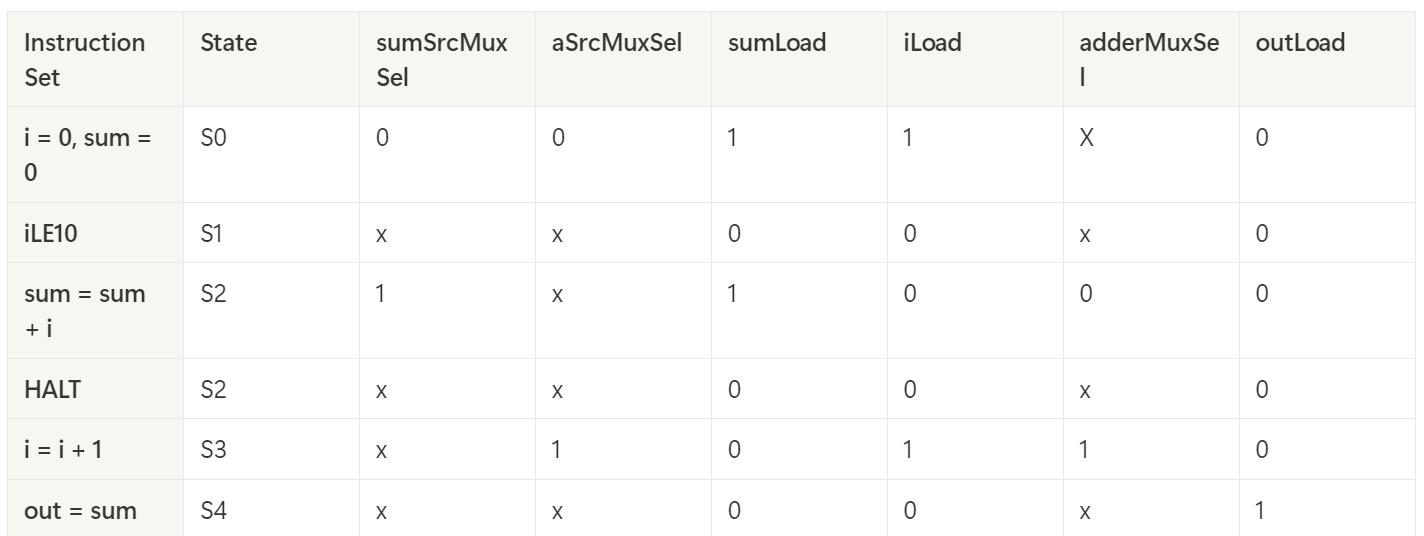
4. code 및 testbench simulation 결과
- adder_0_10.v
더보기
`timescale 1ns / 1ps
module adder_0_10 (
    input         clk,
    input         rst,
    output [15:0] outPort
    // output [3:0] fndCom,
    // output [7:0] fndFont
);
    wire w_iLE10, w_sumSrcMuxSel, w_iSrcMuxSel, w_sumLoad, w_iLoad, w_outLoad, w_adderSrcMuxSel;
    wire [15:0] w_outPort;

    controlUnit U_controlUnit (
        .clk           (clk),
        .rst           (rst),
        .iLE10         (w_iLE10),
        .sumSrcMuxSel  (w_sumSrcMuxSel),
        .iSrcMuxSel    (w_iSrcMuxSel),
        .sumLoad       (w_sumLoad),
        .iLoad         (w_iLoad),
        .outLoad       (w_outLoad),
        .adderSrcMuxSel(w_adderSrcMuxSel)
    );

    datapath U_datapath (
        .clk           (clk),
        .rst           (rst),
        .sumSrcMuxSel  (w_sumSrcMuxSel),
        .iSrcMuxSel    (w_iSrcMuxSel),
        .sumLoad       (w_sumLoad),
        .iLoad         (w_iLoad),
        .outLoad       (w_outLoad),
        .adderSrcMuxSel(w_adderSrcMuxSel),
        .iLE10         (w_iLE10),
        .outPort       (outPort)
    );
/*
    fnd_controller U_fnd(
        .i_con_clk(clk),
        .i_con_reset(rst),
        .i_con_bcdData(w_outPort),
        .con_fndCom_o(fndCom),
        .con_fndFont_o(fndFont)
    );   */

endmodule

module controlUnit (
    input      clk,
    input      rst,
    input      iLE10,
    output reg sumSrcMuxSel,
    output reg iSrcMuxSel,
    output reg sumLoad,
    output reg iLoad,
    output reg outLoad,
    output reg adderSrcMuxSel
);
    localparam S0 = 3'd0;
    localparam S1 = 3'd1;
    localparam S2 = 3'd2;
    localparam S3 = 3'd3;
    localparam S4 = 3'd4;

    reg [2:0] state, state_n;

    always @(posedge clk, posedge rst) begin
        if (rst) begin
            state <= S0;
        end else begin
            state <= state_n;
        end
    end

    always @(*) begin
        state_n = state;
        case (state)
            S0: state_n = S1;
            S1: state_n = S2;
            S2: begin
                if (iLE10) begin
                    state_n = S3;
                end else begin
                    state_n = S2;
                end
            end
            S3: state_n = S4;
            S4: state_n = S1;
        endcase
    end

    always @(*) begin
        sumSrcMuxSel   = 1'b0;
        iSrcMuxSel     = 1'b0;
        sumLoad        = 1'b0;
        iLoad          = 1'b0;
        adderSrcMuxSel = 1'b0;
        outLoad        = 1'b0;
        case (state)
            S0: begin
                sumSrcMuxSel   = 1'b0;
                iSrcMuxSel     = 1'b0;
                sumLoad        = 1'b1;
                iLoad          = 1'b1;
                adderSrcMuxSel = 1'b0;
                outLoad        = 1'b0;
            end
            S1: begin
                sumSrcMuxSel   = 1'b0;
                iSrcMuxSel     = 1'b0;
                sumLoad        = 1'b0;
                iLoad          = 1'b0;
                adderSrcMuxSel = 1'b0;
                outLoad        = 1'b0;
            end
            S2: begin
                if (iLE10) begin
                    sumSrcMuxSel   = 1'b1;
                    iSrcMuxSel     = 1'b0;
                    sumLoad        = 1'b1;
                    iLoad          = 1'b0;
                    adderSrcMuxSel = 1'b0;
                    outLoad        = 1'b0;
                end else begin
                    sumSrcMuxSel   = 1'b0;
                    iSrcMuxSel     = 1'b0;
                    sumLoad        = 1'b0;
                    iLoad          = 1'b0;
                    adderSrcMuxSel = 1'b0;
                    outLoad        = 1'b0;
                end
            end
            S3: begin
                sumSrcMuxSel   = 1'b0;
                iSrcMuxSel     = 1'b1;
                sumLoad        = 1'b0;
                iLoad          = 1'b1;
                adderSrcMuxSel = 1'b1;
                outLoad        = 1'b0;
            end
            S4: begin
                sumSrcMuxSel   = 1'b0;
                iSrcMuxSel     = 1'b0;
                sumLoad        = 1'b0;
                iLoad          = 1'b0;
                adderSrcMuxSel = 1'b0;
                outLoad        = 1'b1;
            end
            default: ;
        endcase
    end

endmodule

module datapath (
    input         clk,
    input         rst,
    input         sumSrcMuxSel,
    input         iSrcMuxSel,
    input         sumLoad,
    input         iLoad,
    input         outLoad,
    input         adderSrcMuxSel,
    output        iLE10,
    output [15:0] outPort
);

    wire [15:0] w_adderResult, w_adderMuxOut, w_sumMuxOut, w_iMuxOut, w_sumRegOut, w_iRegOut;

    mux_2x1 U_sumMux (
        .sel(sumSrcMuxSel),
        .x0 (16'b0),
        .x1 (w_adderResult),
        .y  (w_sumMuxOut)
    );

    mux_2x1 U_iMux (
        .sel(iSrcMuxSel),
        .x0 (16'b0),
        .x1 (w_adderResult),
        .y  (w_iMuxOut)
    );

    mux_2x1 U_adderMux (
        .sel(adderSrcMuxSel),
        .x0 (w_sumRegOut),
        .x1 (16'b1),
        .y  (w_adderMuxOut)
    );

    register U_sumReg (
        .clk (clk),
        .rst (rst),
        .load(sumLoad),
        .d   (w_sumMuxOut),
        .q   (w_sumRegOut)
    );

    register U_iReg (
        .clk (clk),
        .rst (rst),
        .load(iLoad),
        .d   (w_iMuxOut),
        .q   (w_iRegOut)
    );

    comparator U_comp (
        .a (w_iRegOut),
        .b (16'd10),
        .le(iLE10)
    );

    adder U_adder (
        .a  (w_adderMuxOut),
        .b  (w_iRegOut),
        .sum(w_adderResult)
    );

    register U_outReg (
        .clk (clk),
        .rst (rst),
        .load(outLoad),
        .d   (w_sumRegOut),
        .q   (outPort)
    );

endmodule

module mux_2x1 (
    input             sel,
    input      [15:0] x0,
    input      [15:0] x1,
    output reg [15:0] y
);

    always @(*) begin
        case (sel)
            1'b0: y = x0;
            1'b1: y = x1;
            default: y = 8'bx;
        endcase
    end
endmodule

module register (
    input         clk,
    input         rst,
    input         load,
    input  [15:0] d,
    output [15:0] q
);
    reg [15:0] q_reg;
    assign q = q_reg;

    always @(posedge clk, posedge rst) begin
        if (rst) begin
            q_reg <= 0;
        end else begin
            if (load) begin
                q_reg <= d;
            end
        end
    end
endmodule

module comparator (
    input  [15:0] a,
    input  [15:0] b,
    output [15:0] le
);

    assign le = (a <= b);

endmodule

module adder (
    input  [15:0] a,
    input  [15:0] b,
    output [15:0] sum
);

    assign sum = a + b;

endmodule- elaborated schematic

- testbench simulation
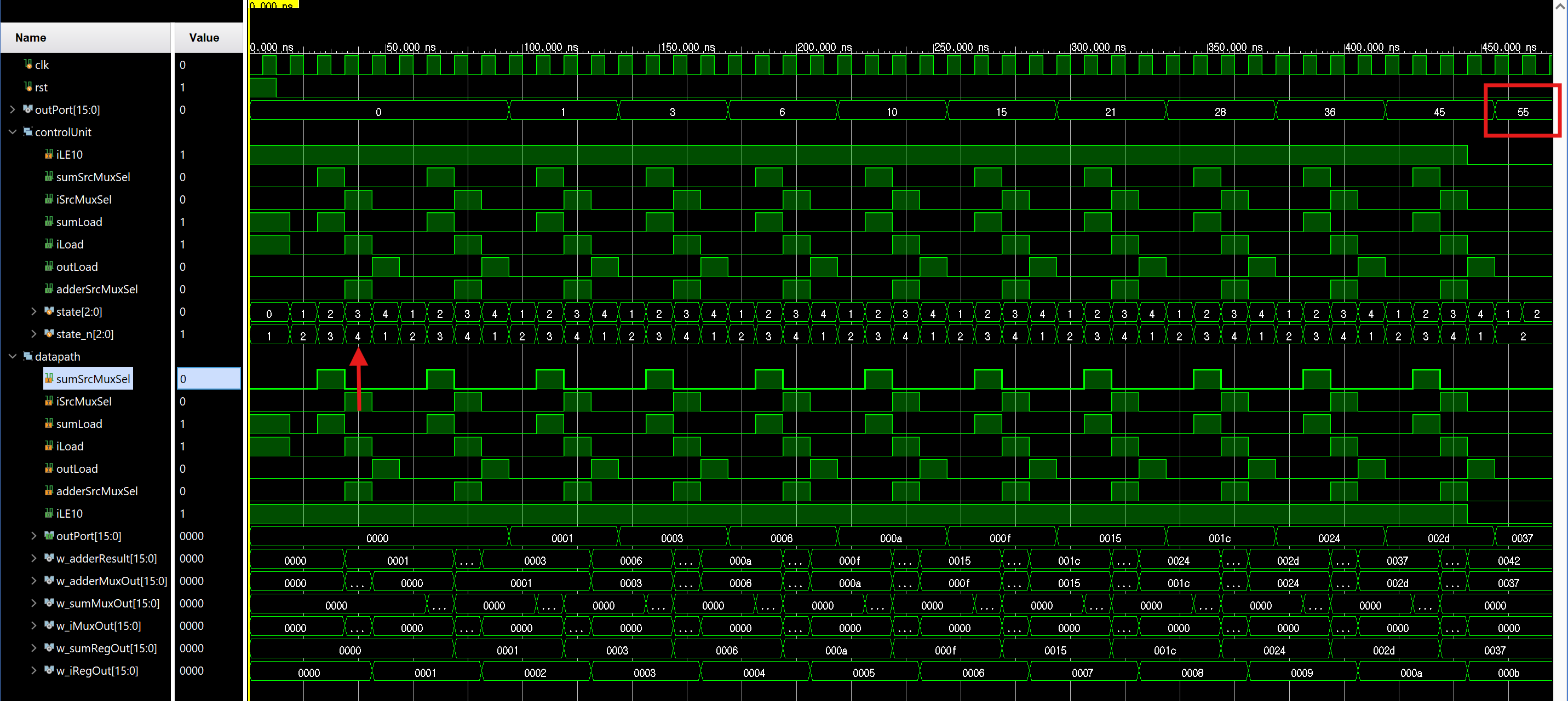
작성한 asm chart에 따라 state가 잘 넘어가고, 마지막 출력값으로 55가 나오는 것을 알 수 있다.
💡 Register File
이때까지 register가 한 line이였다면 이제는 메모리 형태로 사용
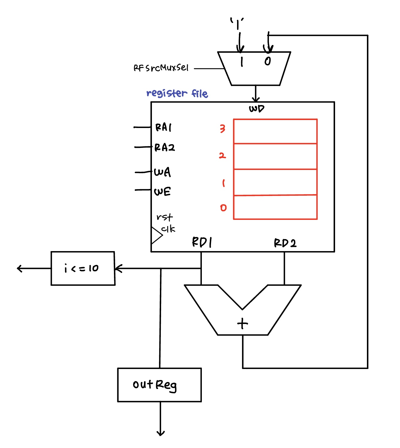
register file 에서는 reset이 존재하지 x, H/W 적으로 초기화시키지 않고 S/W 적으로 초기화시킴
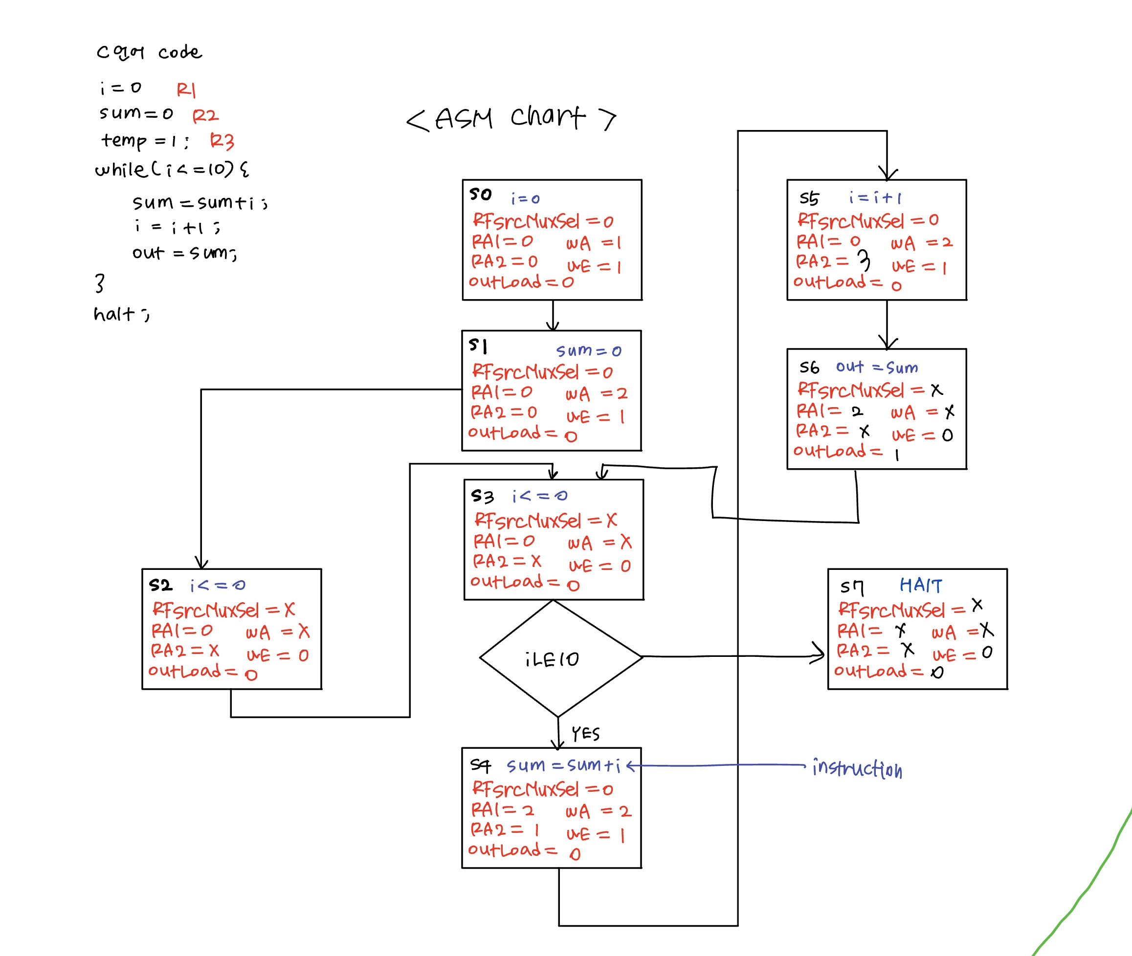
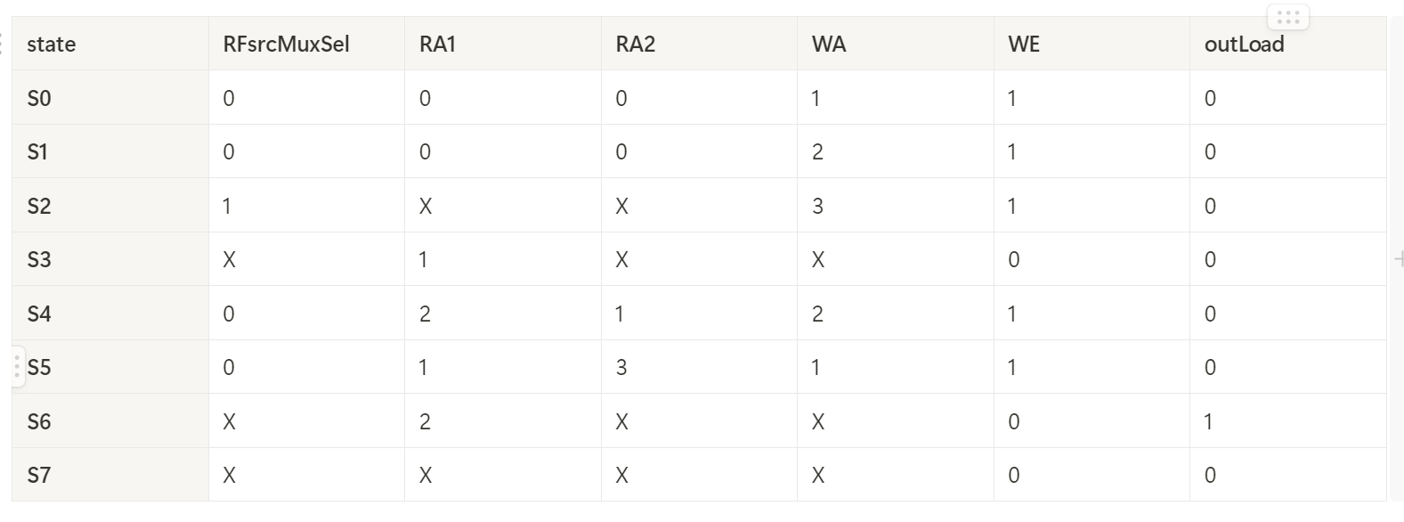
- testbench simulation

- code
더보기
`timescale 1ns / 1ps

module dedicated_processor (
    input         clk,
    input         rst,
    output [15:0] outPort
);

    wire w_iLE10, w_RFsrcMuxSel, w_RFwEnable, w_outLoad;
    wire [15:0] w_wAddr, w_rAddr1, w_rAddr2;

    controlUnit U_controlUnit (
        .clk        (clk),
        .rst        (rst),
        .iLE10      (w_iLE10),
        .RFsrcMuxSel(w_RFsrcMuxSel),
        .RFwEnable  (w_RFwEnable),
        .wAddr      (w_wAddr),
        .rAddr1     (w_rAddr1),
        .rAddr2     (w_rAddr2),
        .outLoad    (w_outLoad)
    );

    dataPath U_datapath (
        .clk        (clk),
        .rst        (rst),
        .RFsrcMuxSel(w_RFsrcMuxSel),
        .RFwEnable  (w_RFwEnable),
        .wAddr      (w_wAddr),
        .rAddr1     (w_rAddr1),
        .rAddr2     (w_rAddr2),
        .outLoad    (w_outLoad),
        .iLE10      (w_iLE10),
        .outPort    (outPort)
    );

endmodule

module controlUnit (
    input        clk,
    input        rst,
    input        iLE10,
    output       RFsrcMuxSel,
    output       RFwEnable,
    output [1:0] wAddr,
    output [1:0] rAddr1,
    output [1:0] rAddr2,
    output       outLoad
);

    localparam S0 = 3'd0;
    localparam S1 = 3'd1;
    localparam S2 = 3'd2;
    localparam S3 = 3'd3;
    localparam S4 = 3'd4;
    localparam S5 = 3'd5;
    localparam S6 = 3'd6;
    localparam S7 = 3'd7;

    reg [2:0] state, state_next;
    reg [8:0] controlSignal;

    assign {RFsrcMuxSel, rAddr1, rAddr2, wAddr, RFwEnable, outLoad} = controlSignal;

    always @(posedge clk, posedge rst) begin
        if (rst) begin
            state <= S0;
        end else begin
            state <= state_next;
        end
    end

    always @(*) begin
        state_next = state;
        case (state)
            S0: state_next = S1;
            S1: state_next = S2;
            S2: state_next = S3;
            S3: begin
                if (iLE10) begin
                    state_next = S4;
                end else state_next = S7;
            end
            S4: state_next = S5;
            S5: state_next = S6;
            S6: state_next = S3;
            S7: state_next = S7;
        endcase
    end

    always @(*) begin
        controlSignal = 9'b0;
        case (state)
            S0: controlSignal = 9'b0_00_00_01_1_0;
            S1: controlSignal = 9'b0_00_00_10_1_0;
            S2: controlSignal = 9'b1_00_00_11_1_0;
            S3: controlSignal = 9'b0_01_00_00_0_0;
            S4: controlSignal = 9'b0_10_01_10_1_0;
            S5: controlSignal = 9'b0_01_11_01_1_0;
            S6: controlSignal = 9'b0_10_00_00_0_1;
            S7: controlSignal = 9'b0_00_00_00_0_0;
        endcase
    end
endmodule

module dataPath (
    input         clk,
    input         rst,
    input         RFsrcMuxSel,
    input         RFwEnable,
    input  [ 1:0] wAddr,
    input  [ 1:0] rAddr1,
    input  [ 1:0] rAddr2,
    input         outLoad,
    output        iLE10,
    output [15:0] outPort
);

    wire [15:0] w_adderResult, w_RFSrcMuxOut, w_rData1, w_rData2;

    mux_2x1 U_regFileMux (
        .sel(RFsrcMuxSel),
        .x0 (w_adderResult),
        .x1 (16'd1),
        .y  (w_RFSrcMuxOut)
    );

    registerFile U_regFile (
        .clk    (clk),
        .wEnable(RFwEnable),
        .wAddr  (wAddr),
        .rAddr1 (rAddr1),
        .rAddr2 (rAddr2),
        .wData  (w_RFSrcMuxOut),
        .rData1 (w_rData1),
        .rData2 (w_rData2)
    );

    comparator U_comp (
        .a (w_rData1),
        .b (16'd10),
        .le(iLE10)
    );

    adder U_adder (
        .a  (w_rData1),
        .b  (w_rData2),
        .sum(w_adderResult)
    );

    register U_outReg (
        .clk (clk),
        .rst (rst),
        .load(outLoad),
        .d   (w_rData1),
        .q   (outPort)
    );

endmodule

module registerFile (  // ram 같은 메모리, rst이 없는 register 묶음
    input         clk,
    input         wEnable,
    input  [ 1:0] wAddr,
    input  [ 1:0] rAddr1,
    input  [ 1:0] rAddr2,
    input  [15:0] wData,
    output [15:0] rData1,
    output [15:0] rData2
);
    reg [15:0] regFile[0:3];

    always @(posedge clk) begin
        if (wEnable) begin
            regFile[wAddr] <= wData;
        end
    end

    assign rData1 = (rAddr1 != 0) ? regFile[rAddr1] : 0;
    assign rData2 = (rAddr2 != 0) ? regFile[rAddr2] : 0;

endmodule

module mux_2x1 (
    input             sel,
    input      [15:0] x0,
    input      [15:0] x1,
    output reg [15:0] y
);

    always @(*) begin
        case (sel)
            1'b0: y = x0;
            1'b1: y = x1;
            default: y = 8'bx;
        endcase
    end
endmodule

module register (
    input         clk,
    input         rst,
    input         load,
    input  [15:0] d,
    output [15:0] q
);
    reg [15:0] q_reg;
    assign q = q_reg;

    always @(posedge clk, posedge rst) begin
        if (rst) begin
            q_reg <= 0;
        end else begin
            if (load) begin
                q_reg <= d;
            end
        end
    end
endmodule

module comparator (
    input  [15:0] a,
    input  [15:0] b,
    output [15:0] le
);

    assign le = (a <= b);

endmodule

module adder (
    input  [15:0] a,
    input  [15:0] b,
    output [15:0] sum
);

    assign sum = a + b;

endmodule
'하만 세미콘 아카데미 8기 > verilog 설계' 카테고리의 다른 글
| 241205 cpu 설계 기초 (0) | 2024.12.06 |
|---|---|
| 241106 - verilog 기초 3 (+Counter) (0) | 2024.11.07 |
| 241104 verilog 기초 1 (+gate, adder) (0) | 2024.11.07 |
| 241105 verilog 기초 2 (+fnd controller) (0) | 2024.11.07 |
