
💡 CPU
1. cpu 종류
- CISC (Complex Intstruction Set Computer)
- micro processor에게 명령을 내리는데 필요한 모든 명령어 셋을 갖추고 있는 processor
- 복잡하고 기능이 많은 명령어로 구성
- RISC (Reduced Instruction Set Computer) → cisc에 비해 instruction set이 적다 → 명령어가 간략화, 단순화된 형태
- cisc 내부의 20%에 해당하는 명령어들만이 전체 80%이상의 일을 처리한다.
- cisc의 복잡한 명령어를 적은 개수의 명령어로 구현하다 보니 clk이 많이 필요하기는 하다.
- ex) cisc에서 하나의 명령어를 risc에서는 3개, 등의 명령어로 여러 번 나누어 구현하게 됨
2. cpu 구조
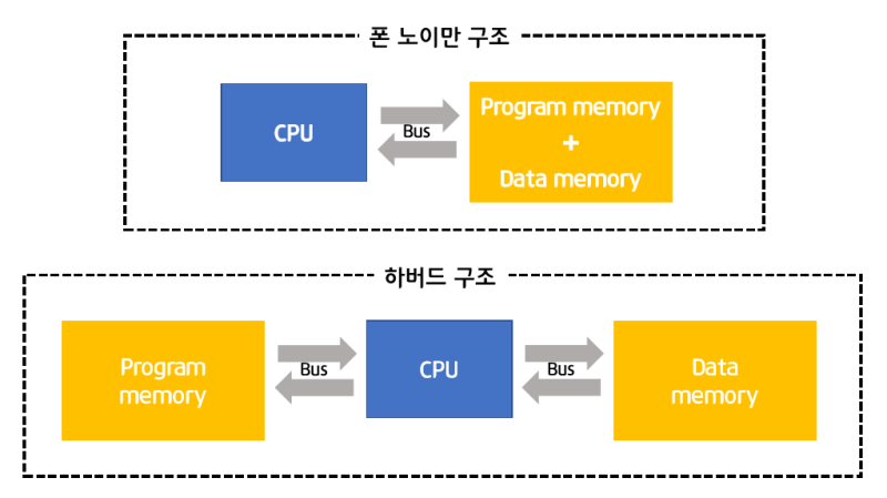
- 폰노이만 구조

- 범용 pc 에서 주로 사용됨
- instruction set이 memory unit에 저장됨
- memory unit에 사용할 program 올려 control unit에서 동작시킴
* memory unit = program memory + data memory
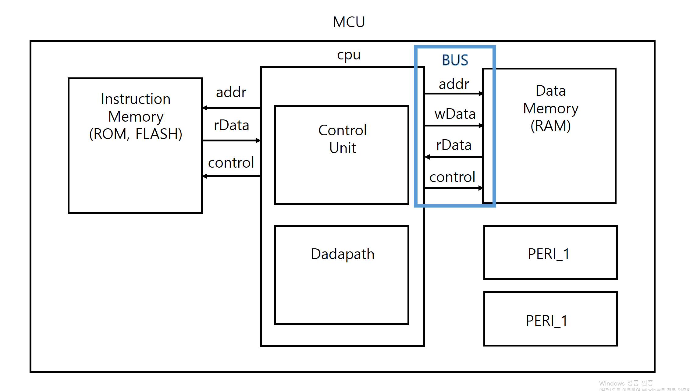
- 하버드 구조

- 주로 임베디드 용도로 사용 (특정 용도, asic)
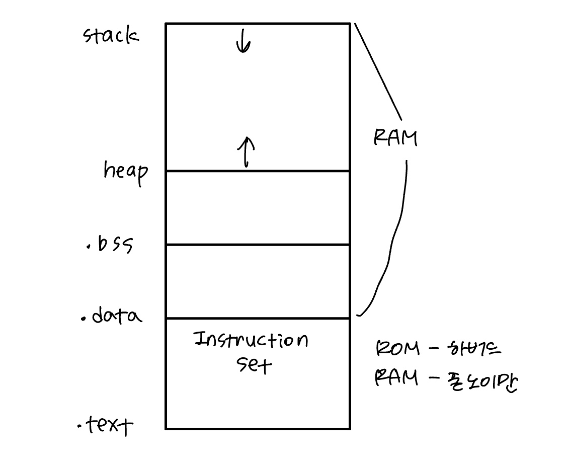
- instruction(program) memory(ROM, FLASH)와 data memory(RAM)가 분리되어 있음
- 실행 명령어는 program memory, 변수 등은 data memory에 저장
💡 CPU 설계
위와 같은 하버드 구조를 기준으로 하여 설계를 해보자.
1. counter 설계
0 ~ 9까지 카운트하는 시스템 설계
- control unit : state 및 datapath에서의 로직들의 동작 신호를 제어
- datapath : control unit에서의 신호에 따라 연산 및 데이터 전달 처리
1) datapath 설계
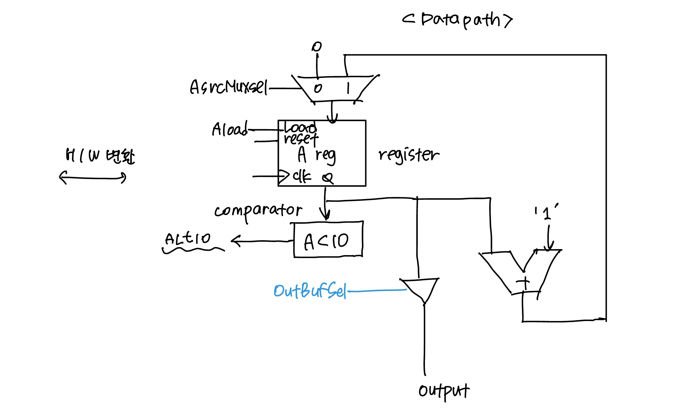
↓ datapath 코드
module dataPath (
    input        clk,
    input        rst,
    input        aSrcMuxSel,
    input        aLoad,
    input        outBufSel,
    output       ALt10,
    output [7:0] outPort
);

    wire [7:0] w_adderResult, w_aSrcMuxOut, w_aRegOut;

    mux_2x1 U_aSrcMux (
        .sel(aSrcMuxSel),
        .x0 (8'b0),
        .x1 (w_adderResult),
        .y  (w_aSrcMuxOut)
    );

    register_8bit U_aReg (
        .clk (clk),
        .rst (rst),
        .load(aLoad),
        .d   (w_aSrcMuxOut),
        .q   (w_aRegOut)
    );

    comparator U_comp (
        .a (w_aRegOut),
        .b (8'd10),
        .lt(ALt10)
    );

    adder_8bit U_adder (
        .a(w_aRegOut),
        .b(8'd1),
        .y(w_adderResult)
    );

    outBuf U_outBuf (
        .clk(clk),
        .rst(rst),
        .sel(outBufSel),
        .x  (w_aRegOut),
        .y  (outPort)
    );

endmodule

module mux_2x1 (
    input            sel,
    input      [7:0] x0,
    input      [7:0] x1,
    output reg [7:0] y
);

    always @(*) begin
        case (sel)
            1'b0: y = x0;
            1'b1: y = x1;
            default: y = 8'bx;
        endcase
    end
endmodule

module register_8bit (
    input        clk,
    input        rst,
    input        load,
    input  [7:0] d,
    output [7:0] q
);
    reg [7:0] q_reg;

    assign q = q_reg;

    always @(posedge clk, posedge rst) begin
        if (rst) begin
            q_reg <= 0;
        end else begin
            if (load) begin
                q_reg <= d;
            end
        end
    end
endmodule

module comparator (
    input  [7:0] a,
    input  [7:0] b,
    output       lt
);

    assign lt = (a < b);

endmodule

module adder_8bit (
    input  [7:0] a,
    input  [7:0] b,
    output [7:0] y
);
    // carry 사용 x
    assign y = a + b;

endmodule

module outBuf (
    input        clk,
    input        rst,
    input        sel,
    input  [7:0] x,
    output [7:0] y
);

    reg [7:0] y_reg;
    assign y = y_reg;

    always @(posedge clk, posedge rst) begin
        if (rst) begin
            y_reg <= 0;
        end else begin
            if (sel) begin
                y_reg <= x;
            end
        end
    end
endmodule
2. control unit
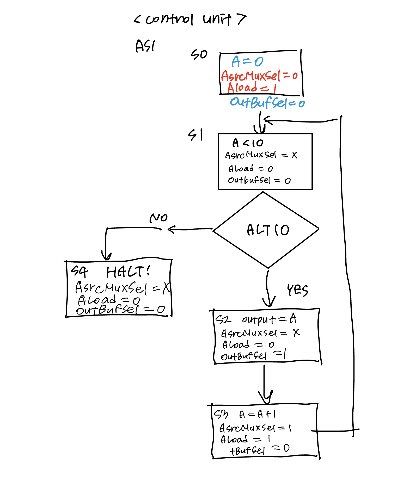
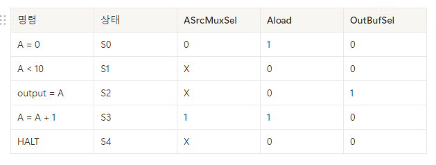
↓ control unit 코드
module controlUnit (
    input      clk,
    input      rst,
    input      ALt10,
    output reg aSrcMuxSel,
    output reg aLoad,
    output reg outBufSel
);

    localparam S0 = 0;
    localparam S1 = 1;
    localparam S2 = 2;
    localparam S3 = 3;
    localparam S4 = 4;

    reg [2:0] state, state_next;

    always @(posedge clk, posedge rst) begin
        if (rst) begin
            state <= S0;
        end else begin
            state <= state_next;
        end
    end

    always @(*) begin
        state_next = state;
        case (state)
            S0: begin
                state_next = S1;
            end
            S1: begin
                if (ALt10) state_next = S2;
                else state_next = S4;
            end
            S2: begin
                state_next = S3;
            end
            S3: begin
                state_next = S1;
            end
            S4: begin
                state_next = S4;
            end
        endcase
    end

    always @(*) begin
        aSrcMuxSel = 1'b0;
        aLoad      = 1'b0;
        outBufSel  = 1'b0;
        case (state)
            S0: begin
                aSrcMuxSel = 1'b0;
                aLoad      = 1'b1;
                outBufSel  = 1'b0;
            end
            S1: begin
                aSrcMuxSel = 1'b0;
                aLoad      = 1'b0;
                outBufSel  = 1'b0;
            end
            S2: begin
                aSrcMuxSel = 1'b0;
                aLoad      = 1'b0;
                outBufSel  = 1'b1;
            end
            S3: begin
                aSrcMuxSel = 1'b1;
                aLoad      = 1'b1;
                outBufSel  = 1'b0;
            end
            S4: begin
                aSrcMuxSel = 1'b0;
                aLoad      = 1'b0;
                outBufSel  = 1'b0;
            end
        endcase
    end

endmodule
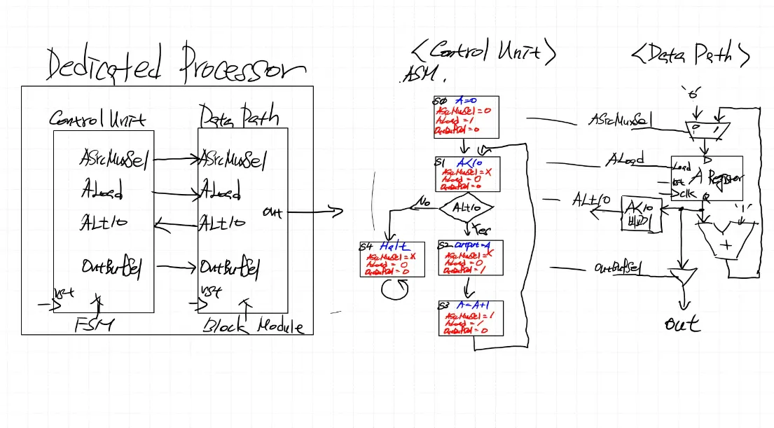
3. top 연결
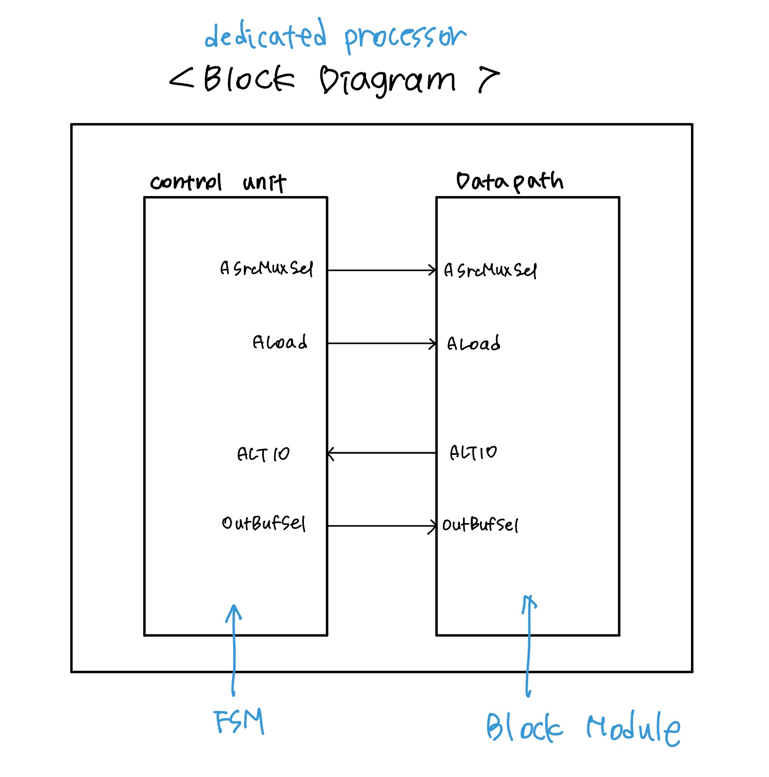
block diagram에 따라 control unit과 datapath를 연결
↓ dedicated_processor 코드
module dedicated_processor (
    input        clk,
    input        rst,
    output [7:0] outPort
);

    wire w_ALt10, w_aSrcMuxsel, w_aLoad, w_outBufSel;

    controlUnit U_controlUnit (
        .clk       (clk),
        .rst       (rst),
        .ALt10     (w_ALt10),
        .aSrcMuxSel(w_aSrcMuxSel),
        .aLoad     (w_aLoad),
        .outBufSel (w_outBufSel)
    );

    dataPath U_dataPath (
        .clk       (clk),
        .rst       (rst),
        .aSrcMuxSel(w_aSrcMuxSel),
        .aLoad     (w_aLoad),
        .outBufSel (w_outBufSel),
        .ALt10     (w_ALt10),
        .outPort   (outPort)
    );

endmodule
'하만 세미콘 아카데미 8기 > verilog 설계' 카테고리의 다른 글
| 241206 cpu 설계 기초 2 (0) | 2024.12.07 |
|---|---|
| 241106 - verilog 기초 3 (+Counter) (0) | 2024.11.07 |
| 241104 verilog 기초 1 (+gate, adder) (0) | 2024.11.07 |
| 241105 verilog 기초 2 (+fnd controller) (0) | 2024.11.07 |
💡 CPU
1. cpu 종류
- CISC (Complex Intstruction Set Computer)
- micro processor에게 명령을 내리는데 필요한 모든 명령어 셋을 갖추고 있는 processor
- 복잡하고 기능이 많은 명령어로 구성
- RISC (Reduced Instruction Set Computer) → cisc에 비해 instruction set이 적다 → 명령어가 간략화, 단순화된 형태
- cisc 내부의 20%에 해당하는 명령어들만이 전체 80%이상의 일을 처리한다.
- cisc의 복잡한 명령어를 적은 개수의 명령어로 구현하다 보니 clk이 많이 필요하기는 하다.
- ex) cisc에서 하나의 명령어를 risc에서는 3개, 등의 명령어로 여러 번 나누어 구현하게 됨
2. cpu 구조
- 폰노이만 구조
- 범용 pc 에서 주로 사용됨
- instruction set이 memory unit에 저장됨
- memory unit에 사용할 program 올려 control unit에서 동작시킴
* memory unit = program memory + data memory
- 하버드 구조
- 주로 임베디드 용도로 사용 (특정 용도, asic)
- instruction(program) memory(ROM, FLASH)와 data memory(RAM)가 분리되어 있음
- 실행 명령어는 program memory, 변수 등은 data memory에 저장
💡 CPU 설계
위와 같은 하버드 구조를 기준으로 하여 설계를 해보자.
1. counter 설계
0 ~ 9까지 카운트하는 시스템 설계
- control unit : state 및 datapath에서의 로직들의 동작 신호를 제어
- datapath : control unit에서의 신호에 따라 연산 및 데이터 전달 처리
1) datapath 설계
↓ datapath 코드
module dataPath (
    input        clk,
    input        rst,
    input        aSrcMuxSel,
    input        aLoad,
    input        outBufSel,
    output       ALt10,
    output [7:0] outPort
);

    wire [7:0] w_adderResult, w_aSrcMuxOut, w_aRegOut;

    mux_2x1 U_aSrcMux (
        .sel(aSrcMuxSel),
        .x0 (8'b0),
        .x1 (w_adderResult),
        .y  (w_aSrcMuxOut)
    );

    register_8bit U_aReg (
        .clk (clk),
        .rst (rst),
        .load(aLoad),
        .d   (w_aSrcMuxOut),
        .q   (w_aRegOut)
    );

    comparator U_comp (
        .a (w_aRegOut),
        .b (8'd10),
        .lt(ALt10)
    );

    adder_8bit U_adder (
        .a(w_aRegOut),
        .b(8'd1),
        .y(w_adderResult)
    );

    outBuf U_outBuf (
        .clk(clk),
        .rst(rst),
        .sel(outBufSel),
        .x  (w_aRegOut),
        .y  (outPort)
    );

endmodule

module mux_2x1 (
    input            sel,
    input      [7:0] x0,
    input      [7:0] x1,
    output reg [7:0] y
);

    always @(*) begin
        case (sel)
            1'b0: y = x0;
            1'b1: y = x1;
            default: y = 8'bx;
        endcase
    end
endmodule

module register_8bit (
    input        clk,
    input        rst,
    input        load,
    input  [7:0] d,
    output [7:0] q
);
    reg [7:0] q_reg;

    assign q = q_reg;

    always @(posedge clk, posedge rst) begin
        if (rst) begin
            q_reg <= 0;
        end else begin
            if (load) begin
                q_reg <= d;
            end
        end
    end
endmodule

module comparator (
    input  [7:0] a,
    input  [7:0] b,
    output       lt
);

    assign lt = (a < b);

endmodule

module adder_8bit (
    input  [7:0] a,
    input  [7:0] b,
    output [7:0] y
);
    // carry 사용 x
    assign y = a + b;

endmodule

module outBuf (
    input        clk,
    input        rst,
    input        sel,
    input  [7:0] x,
    output [7:0] y
);

    reg [7:0] y_reg;
    assign y = y_reg;

    always @(posedge clk, posedge rst) begin
        if (rst) begin
            y_reg <= 0;
        end else begin
            if (sel) begin
                y_reg <= x;
            end
        end
    end
endmodule
2. control unit
↓ control unit 코드
module controlUnit (
    input      clk,
    input      rst,
    input      ALt10,
    output reg aSrcMuxSel,
    output reg aLoad,
    output reg outBufSel
);

    localparam S0 = 0;
    localparam S1 = 1;
    localparam S2 = 2;
    localparam S3 = 3;
    localparam S4 = 4;

    reg [2:0] state, state_next;

    always @(posedge clk, posedge rst) begin
        if (rst) begin
            state <= S0;
        end else begin
            state <= state_next;
        end
    end

    always @(*) begin
        state_next = state;
        case (state)
            S0: begin
                state_next = S1;
            end
            S1: begin
                if (ALt10) state_next = S2;
                else state_next = S4;
            end
            S2: begin
                state_next = S3;
            end
            S3: begin
                state_next = S1;
            end
            S4: begin
                state_next = S4;
            end
        endcase
    end

    always @(*) begin
        aSrcMuxSel = 1'b0;
        aLoad      = 1'b0;
        outBufSel  = 1'b0;
        case (state)
            S0: begin
                aSrcMuxSel = 1'b0;
                aLoad      = 1'b1;
                outBufSel  = 1'b0;
            end
            S1: begin
                aSrcMuxSel = 1'b0;
                aLoad      = 1'b0;
                outBufSel  = 1'b0;
            end
            S2: begin
                aSrcMuxSel = 1'b0;
                aLoad      = 1'b0;
                outBufSel  = 1'b1;
            end
            S3: begin
                aSrcMuxSel = 1'b1;
                aLoad      = 1'b1;
                outBufSel  = 1'b0;
            end
            S4: begin
                aSrcMuxSel = 1'b0;
                aLoad      = 1'b0;
                outBufSel  = 1'b0;
            end
        endcase
    end

endmodule
3. top 연결
block diagram에 따라 control unit과 datapath를 연결
↓ dedicated_processor 코드
module dedicated_processor (
    input        clk,
    input        rst,
    output [7:0] outPort
);

    wire w_ALt10, w_aSrcMuxsel, w_aLoad, w_outBufSel;

    controlUnit U_controlUnit (
        .clk       (clk),
        .rst       (rst),
        .ALt10     (w_ALt10),
        .aSrcMuxSel(w_aSrcMuxSel),
        .aLoad     (w_aLoad),
        .outBufSel (w_outBufSel)
    );

    dataPath U_dataPath (
        .clk       (clk),
        .rst       (rst),
        .aSrcMuxSel(w_aSrcMuxSel),
        .aLoad     (w_aLoad),
        .outBufSel (w_outBufSel),
        .ALt10     (w_ALt10),
        .outPort   (outPort)
    );

endmodule
'하만 세미콘 아카데미 8기 > verilog 설계' 카테고리의 다른 글
| 241206 cpu 설계 기초 2 (0) | 2024.12.07 |
|---|---|
| 241106 - verilog 기초 3 (+Counter) (0) | 2024.11.07 |
| 241104 verilog 기초 1 (+gate, adder) (0) | 2024.11.07 |
| 241105 verilog 기초 2 (+fnd controller) (0) | 2024.11.07 |